1.3. Creating Figure Types
A new figure can be built using the figure builder window. Click 'Create Figure Type' in the File menu to open the figure builder window or click the Edit Figure button to edit the selected figure. Click 'New' in the figure builder to start a new figure.
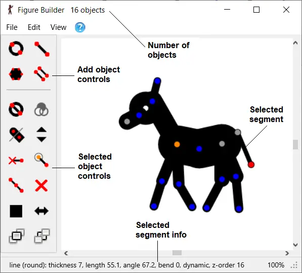
The figure builder window
Figure types are built from lines or circles, called segments, and additionally
polygons. After building a figure type, it can be saved as an
STK file from the File menu to share with others or use later. It can also be added directly to the animation by clicking 'Add To Animation' in the File menu and giving the figure a unique name, which will identify it in the figure selector. A unique name will be generated automatically if left blank.
While building a figure, actions can be undone using the undo and redo buttons in the edit menu. The figure can also be positioned using the same methods as described in the
Positioning Figures section, including stretching segments using the Ctrl key and bending lines using the right mouse button.
Information about the selected segment or polygon is displayed at the bottom of the window. This includes the segment type, thickness, length, angle and whether the segment is static or dynamic (see Remove / restore handle below) and the draw order (z-order). The total number of segments and polygons is shown in the title bar at the top of the window.
The selected segment is shown with a red end point handle, while all other segments have blue handles.
Figure Building Controls
The controls for building a figure are to the left of the window and are as follows:

Add a circle
Add a circle segment to the figure type. After clicking the button, click any of the handles to select the joint it should pivot on and then click anywhere to set the length and angle of the segment.

Add a line
Add a line segment to the figure type. After clicking the button, click any of the handles to select the joint it should pivot on and then click anywhere to set the length and angle of the segment.

Add a polygon
Add a
polygon to the figure type by connecting previously created handles.
This is useful for filling areas between segments with solid areas of colour. After clicking the button, begin clicking handles in order to create the polygon. Finish by clicking the first handle again or clicking the polygon button. A polygon must join a minimum of 3 handles. Polygons will stay connected as the segments they connect to are moved.

Duplicate segment
Duplicate the selected segment. After clicking the button, click on any of the handles on the figure to select the joint the new segment should pivot on. Holding the Ctrl key while clicking the duplicate button will mirror the duplicated segment, or branch if the Shift key is used (see below).

Change segment kind
Toggle the selected segment between a line and a circle. All other segment properties will remain unchanged.

Change circle fill
Toggle the selected segment between the three types of circle fill. These are; solid white, clear (no fill) and solid. The solid fill will be the same colour as the figure when changed in an animation, but the white fill will always remain white (as it was in Pivot v2). The button is only enabled when the selected segment is a circle.

Change the end cap of a line segment
Toggle the selected line segment between round end caps and square. The default is round. The button will not be enabled if a line segment is not selected.

Change segment thickness
Change the line thickness of the selected segment by 1 screen pixel. Hold down the Ctrl key while clicking and the thickness will change by 5 pixels for more rapid adjustment. A line of zero thickness will be invisible when unselected and when used in the animation. Zoom in before changing the thickness to make finer adjustments.

Remove / restore handle
Make the selected segment 'static' or 'dynamic'. A static segment will not have a handle at its end point when the figure has been added to the animation editing area. All segments are dynamic by default. A static segment will have a grey handle when not selected and a white handle when selected. This is useful when building detailed figures to reduce handle clutter.

Set origin joint
Set the end-point of the selected segment as the origin joint. The origin joint is the point that all other segments branches attach to and shows the orange handle for moving the figure. Changing the origin joint is particularly useful when repositioning the handles for
joining figures at a specific point.

Split segment
Split the selected segment into two segments by inserting a new joint at the segment centre. The resulting two segments will have the same properties as the original segment but will be half the length.

Delete segment or polygon
Delete the selected segment or polygon. If the segment has other segments attached to its end-point, then those segments will drop down to the pivot-point of the deleted segment. If a polygon is joined to deleted segment and results in the polygon having fewer than 3 connections then it will also be deleted.

Colour segment or polygon
Set the colour and opacity of the selected segment or polygon by opening the colour selector. The current colour of the selected segment or polygon is shown on the button. Hold down the Ctrl key while clicking to set the
gradient colour of the selected line or circle segment.

Flip / Mirror the selected segment
Flip the selected segment horizontally or vertically using the Ctrl key. This is especially useful for mirroring sprite image segments, which cannot be done by rotating alone.

Raise segment or polygon
Raise the selected segment or polygon above everything else or raise by one object using the Ctrl key. The draw order (z-order) of the selected segment or polygons can be seen in the status bar at the bottom of the window.

Lower segment or polygon
Lower the selected segment or polygon below everything else or lower by one object using the Ctrl key. The draw order (z-order) of the selected segment or polygons can be seen in the status bar at the bottom of the window.
Operations on Branches
Holding the Shift key while using most of the segment attribute buttons will change the property for the selected segment, but also all segments and polygons connected above it (i.e. the whole branch). This is true of the Duplicate, Circle fill, End cap, Thickness, Remove handle, Split, Delete, Colour, Mirror, Raise and Lower controls. This can save a lot of time when editing a figure. When the Shift key is pressed you will see all the segments in the the selected branch displayed with red handles.
If colouring, duplicating or deleting a branch containing a
polygon, then the polygon will be included in the operation.
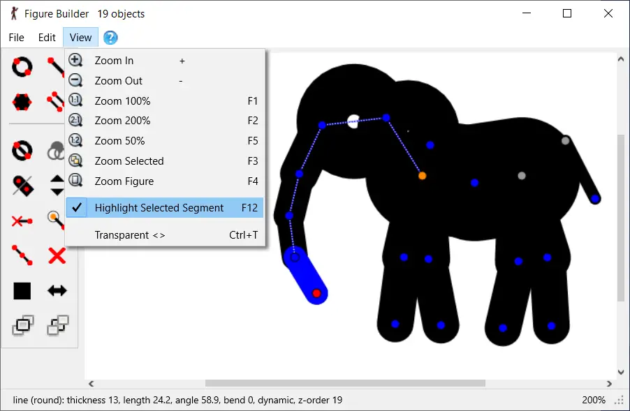
Selected Segment Highlighting
The selected segment is always shown with a red end point handle, while all other segments have blue handles. However, the selected segment can also be highlighted in blue by selecting 'Highlight Selected Segment' from the View menu or by using the F12 keyboard shortcut. The path of segment from the selected segment to the orange origin handle is also shown. This can be useful when working on a complex figure with many overlapping segments. However, it will hide the colour of the selected segment. This option persists after closing and re-opening Pivot.
The figure builder window with selected segment highlighting enabled.
The selected segment is shown in blue and the path to the origin is shown as a line.